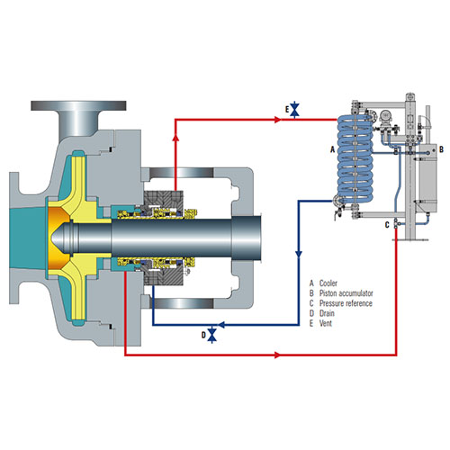
API PLAN 53C
Barrier fluid system pressurized by a piston accumulator supplying clean liquid for an arrangement 3 pressurized dual seal. The barrier
pressure is generated from the seal chamber pressure. The system is self-energizing and reacts to fluctuations in the seal chamber fluid pressure.
Features
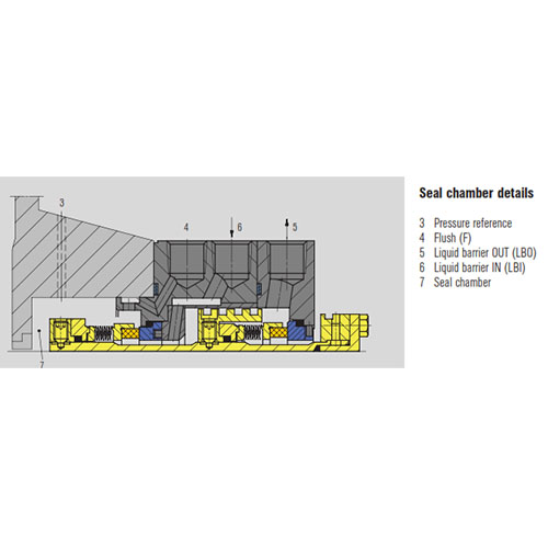
- A piston accumulator dynamically adjusts the barrier pressure which is based on the seal chamber pressure, thus maintaining a fixed, steady differential pressure across the inboard seal faces.
- Barrier liquid enters the process medium through the inner seal faces.
- Uses the seal chamber pressure as a reference pressure and accordingly magnifies the barrier pressure by a pre-defined ratio.
- Highly reliable since there is no need for an external pressure source.
- Heat is removed with the help of a water cooler or an air cooler.
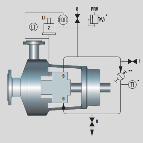
- Uses an internal circulating device to ensure barrier liquid circulation.
Recommended Application
Remarks, Checkpoints :
- Check with the process engineer if product contamination is acceptable.
- Check barrier fluid compatibility with the media.
- Vent the system before start-up. Later ensure that the vent line always remains closed.
- Sense the seal inlet and outlet line temperatures.
- Difference in the temperatures is an indication of proper flow.
- Ensure that the barrier pressure is always higher than the seal chamber pressure by at least 1.4 bar (20 PSI) (for piston ratio selection).
- Since there is less barrier fluid volume in the accumulator, heat dissipation is very much a function of the cooler efficiency.
- Ensure that the seal chamber reference line is not choked and that it is connected to the downstream of the accumulator.
- Ensure proper heating or cooling of the reference pressure line if necessary.
- Check the compatibility of the accumulator materials with the pump media.
Recommended Application :
- For services where product dilution is acceptable.
- For services where media is unsuitable for flushing the inner seal faces.
- For services where Plan 53A cannot be used due to non-availability of a permanent, reliable nitrogen supply.
- Ideal plan for applications with varying seal chamber pressures. Pressure ratio depending on stuffing box pressure range:
- 4 bar (58 PSI) … < 10 bar (145 PSI) = piston ratio 1:1.5
- 10 bar (145 PSI) …< 22 bar (319 PSI) = piston ratio 1:1.2
- 22 bar (319 PSI) … 40 bar (580 PSI) = piston ratio 1:1.1